
Tension Control For Web Offset
Posted: February 19, 2003
Tension Control Illustration
Printed in the "Penrose Annual" 1974
NOTE: John R. Martin is the Owner of Martin Automatic, Inc. In his article he analyzes tension and strength requirements for good register in web offset printing. He also describes the Martin "Inertia Compensated Dancer Roller" and associated equipment that provides printers freedom from dependence on 'paper variation'.
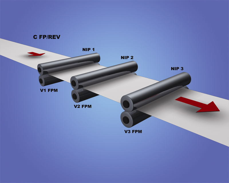
When tension is applied to a rubber band, it stretches; when tension is applied to a steel band, it also stretches, but much less. The relationship between tension and stretch is a function of the material which we will call its modulus. The modulus of paper is not constant; constant tension does not produce constant stretch, nor does constant stretch produce constant tension. It is because of this, and because printers have always tried to hold the wrong thing constant, that the black art of webhandling has remained such a mystery. It is obviously necessary that the web should not break nor accumulate in great loops nor wander sideways. Apart from this, the only reason for maintaining constant tension is the need for good register. The following diagram will help us to analyze cut-to-print register in a perfecting offset press.
Nip 1 will represent the last printing unit, printing one mark per revolution at a speed of V1 feet per minute with a circumference of C feet and therefore printing V1 ÷ C marks per minute. Obviously, if V1 ÷ C marks per minute are being printed, a measurement at any point downstream will yield V1 ÷ C marks per minute also, as we cannot expect to deliver more or fewer signature in a minute than the number we print.
The figure of V1 ÷ C marks per minute must then hold true at Nip 2, which will represent the chill rolls. If, however, the chills are driving the web at a speed of V2 the only way in which V1 ÷ C marks per minute can pass the chills at a speed of V2 feet per minute is for the marks to be spaced (V2 ÷ V 1) C feet apart. Putting the matter another way, we can say that after the marks were printed at a spacing of C feet, the web was stretched by V2 ÷ V1. (V2 ÷ V1 can be less than, equal to, or greater than 1.)
If the web is uniform between Nip 1 and Nip 2, and if the web in the span between Nip 1 and Nip 2 is not subject to any other forces, then the stretch at Nip 2 must apply at all points between Nip 1 and Nip 2. This must be so, because a non-uniform stretch within a span would imply a non-uniform tension within a span and this is impossible because the sum of the forces at any point in the span must equal zero. This means that the spacing of marks in the span between Nip 1 and Nip 2 is equal to (V2÷V1) C just as it is at Nip 2.
Now, if V 1 ÷ V2 is a reasonable value, i.e. if it ensures that the web will not break or accumulate, and if V1 ÷ V2 remains constant both short term and long term, and if the distance which the web travels between Nip 1 and Nip 2 does not change, the registration at the chill rolls will not change. Similarly, subject to the same ifs, the mark spacing between Nip 2 and Nip 3 (Nip 3 representing the folder nip) will be (V3 ÷ V1) C. Thus, the register does not change between Nip 2 and Nip 3 or between Nip 1 and Nip 2; therefore the register does not change between Nip 1 and Nip 3 and cut-to- print register is constant.
Cut-to-print will be constant if:
- The chills drive the web at V1 feet per minute, if all web drive points are non-slip.
Disregarding blanket nips, which are normally non-slip, this condition can be ensured by gripping the web at the drive rollers with sufficient force. The 'trucks' supplied with new presses are normally incapable of supplying enough force. The American firm of Martin Automatic, Inc. supplies high-pressure pneumatically loaded trolleys (trucks), which are self-aligning and capable of ensuring enough traction to prevent slip. - The web is uniform in any given span.
The requirement here is only that the web shall be uniform within a given span, not from roll to roll or within a roll. Fortunately, the modulus of paper, although not constant, is sufficiently uniform within short spans for the error introduced to be well within commercial tolerances. The worst situation is the step-change in modulus that occurs when the outside of a new roll is spliced to the inside of the previous roll. Even then, if all the other ifs are satisfied, the typical error in cut-off can be as small as 1/32 of an inch and return within approximately twenty signatures. - The web in any given span is not subject to any intermediate forces.
The only danger here is that of 'driven' or 'drag' rollers or slitters which have a high gain and significant wrap or trucks. The solution could be simply to idle these rollers, but in practice web-up becomes simpler if they are driven. Therefore, it is recommended that the diameter of these rollers be established at web speed. - The gains are reasonable.
It should be emphasized that reasonable gains have not been predicted by theory but have been determined empirically. For offset perfectors, sufficient experience dictates that folders should drive at bearer speed. For other types of presses and chill rolls on perfectors, the safest route has been to measure precisely the speed of the running web and to match the drive roll gains to the web. For these measurements, Martin Automatic has developed instrumentation with the required precision.
All drive points have a constant relative speed
This requirement can be divided into long-term and short-term aspects. Short-term requirements indicate that drive trains should not show significant 'wrap-up' with changing load, which changes tension. Fortunately, standard printing press design has satisfied this requirement. Long-term requirements indicate the undesirability of adjustable ratio transmissions. In a typical offset perfector, a change in chill roll gain of 0.1% will affect the stretch of the web in the dryer (typically 20 feet) to produce a cut-to-print misregister of 0.1% x 20 ft. (240 in.) = 0.24 in.
It is significant that, in the above analysis, tension was not a consideration. In fact, it emerges clearly that for constant register the stretch between nips must be maintained constant.
Now let us consider color-to-color register using the same diagram, with Nips 1, 2, and 3, which are now representing printing nips. The arguments concerning cut-to-print register still apply, i.e. constant stretch between nips, etc. is still necessary. There is, however, a new difficulty in satisfying the web path between nips.
The web path between nips does not change:
The web will not leave the blankets tangentially, but will 'follow' the blanket in an amount determined by the 'stickiness' of the blankets and the tension in the web. If the blanket stickiness and web tension remains constant, then the web length between units and therefore the color register will remain constant. We still have the requirement of constant stretch between nips and have now added the requirements of constant tension to produce requirements that seem to be mutually exclusive.
How can both tension and stretch between nips be constant when they are related by a variable, i.e. the modulus?
The only way is to set the stretch between nips equal to zero (all printing units 'feed' the same) so that the tension produced by the stretch between nips is zero. Obviously, we cannot print with zero tension, so the web must be pre-tensioned before it enters the first nip (the first printing unit). In other words, whatever tension and stretch exist in the web while it is being printed are established before the web enters the first printing unit and are simply maintained by a one-to-one drive through the units.
In actual practice the application of water to the web tends to reduce the tension as the web passes through the units. Fortunately, this reduction tends to be constant in time, and our requirement for constant tension is not violated -even though the tension between Unit 1 and Unit 2 is not quite the same as that between Units 2 and 3.
To maintain color register, we may further define the web path between nips.
- Stickiness of the blankets remains constant. Experience indicates that normal care in handling inks satisfies this condition adequately
- Tension of the web entering the first printing unit is constant. There are a number of ways to control the tension of the web entering the first printing unit. The indirect method -trying to control tension by controlling stretch -should not be considered, because of the variation of the modulus.
- The web path between nips is constant With the exception of "a" and "b", this requirement reduces to permanently locating all drive and idler rollers.
We now seem to have a formula for good register if our constants can be satisfied. Required stability is seen to be in the order of 0.005% - a figure which is unachievable with conventional variable ratio-transmissions. Martin Automatic has replaced many of these transmissions with constant ratio timing belt drives to produce significant improvements in cut-off register.
For direct control of tension there are two main classes of mechanisms:
- One uses a tension-sensing device and, through an appropriate control system, controls the speed of a nip to maintain the output of the sensor constant. This type of system has no 'storage', and its response-time limits its ability to adjust for rapid changes. Attempts to speed up the response-time and improve the capabilities usually involve complications, which yield no commensurate improvement.
- The other main class of tension control is the dancer or 'floating roller' type of system. The dancer should no be confused with the tension-measuring roller. The dancer does not measure tension -it establishes it. When a tension-measuring roller is out of position by as little as a few thousandths of an inch, usually the tension is different. When a dancer is out of center, this does not mean that the tension is different. Since the dancer establishes tension by pushing on a loop of web, it is desirable that this push should remain constant.
There are three possible sources of error in the design of the dancer:
- Position.
The geometry of the dancer should be established so that the tension is independent of dancer position. In the case of a pivoted dancer, long dancer arms and long web leads help. The dancer should be counterbalanced or move essentially in a vertical direction to minimize gravitational errors. Geometric accuracies better than plus or minus 1/8% are easily achieved. - Speed.
Dancers should be designed so that their push on the web does not change when the dancer is in motion. A well-known example of poor practice is the use of a shock absorber on the dancer, with the aim of stabilizing the system. It is true that many dancer systems require stabilization, but this can be better done with rate response in the control element. - Acceleration.
It has long been realized that a dancer, because of its inertia, will not completely absorb tension transients. Martin Automatic, Inc., with its patented 'Inertia Compensated' dancer roIler, has now made it possible to cancel out the effects of inertia completely. The firm understood that a physically realizable dancer has both rotary and translational inertia and that the effects of these are opposite. The outcome of this understanding is a dancer in which these opposite effects are made equal and, therefore, cancel each other out.
The Martin Inertia Compensated dancer can act as a perfect filter of tension disturbances; upstream transients are absorbed by the dancer and not transmitted downstream. This principle is used in the Martin Constant Tension Infeed and Martin Tension Control.
Conclusion:
Summing up the Martin Automatic experiences, there are two main conclusions to be drawn. The first is that the conventional practice of seeking constant tension at the delivery defeats the requirement of constant stretch (because of the changing modulus). The second is that the common practice of controlling infeed tension with the constant stretch characteristics of an adjustable ratio infeed defeats the requirements for constant tension (again because of changing modulus). The firm hopes it has established that, by controlling the desired parameter, printers can rid themselves of their tremendous dependence on 'paper variation'.